English
 中文简体
 русский
 Español
 عربى





Pair an armored heating cable with a thermocouple that reaches the controller through compensation wire of the matching type and polarity, and the loop will hold its setpoint within a few degrees. Get either half wrong and the controller chases a false number: a reversed or mismatched wire can shift the reading by 50 to 100 °C even when the heater itself is perfectly healthy. The heating cable decides how much energy reaches the pipe, vessel or mold. The compensation wire decides whether the controller knows what that energy has achieved. Specify them together, test them together and document them together.
Short answer
- Size the armored heating cable from calculated heat loss plus a 15 to 25 percent margin, then confirm that sheath temperature and watt density stay inside the limits of both the cable and the process fluid.
- Choose the compensation wire from the thermocouple type: extension grade (X) for base-metal types such as K, J, T, E and N, compensating grade (C) for noble-metal types such as S, R and B.
- Keep the joint between thermocouple and cable below the cable’s rated range, usually 200 °C for extension grades and 100 °C for noble-metal compensating grades.
- Use shielded twisted-pair cable, ground the shield at the controller end only, and keep it at least 300 mm away from heater power cabling.
Armored heating cables and thermocouple compensation wires belong to one loop
A heated process line has two jobs running in parallel. The heating branch converts electrical power into heat. The sensing branch converts temperature into a voltage of a few millivolts and carries it back to the controller. The two cables never connect electrically, yet they live in the same hot, damp, vibrating environment, and a fault in either one produces the same symptom on the plant floor: the line is too hot or too cold and nobody trusts the display.
Thinking of them as one system changes how you buy. The heating cable is specified by sheath alloy, watt density, voltage and length. The compensation wire is specified by thermocouple type, grade, insulation, shielding and temperature range. Procurement often handles the two on separate purchase orders, which is how a type K thermocouple ends up wired with type J cable on the day of commissioning. The diagram below shows where each decision sits.
What makes an armored heating cable different
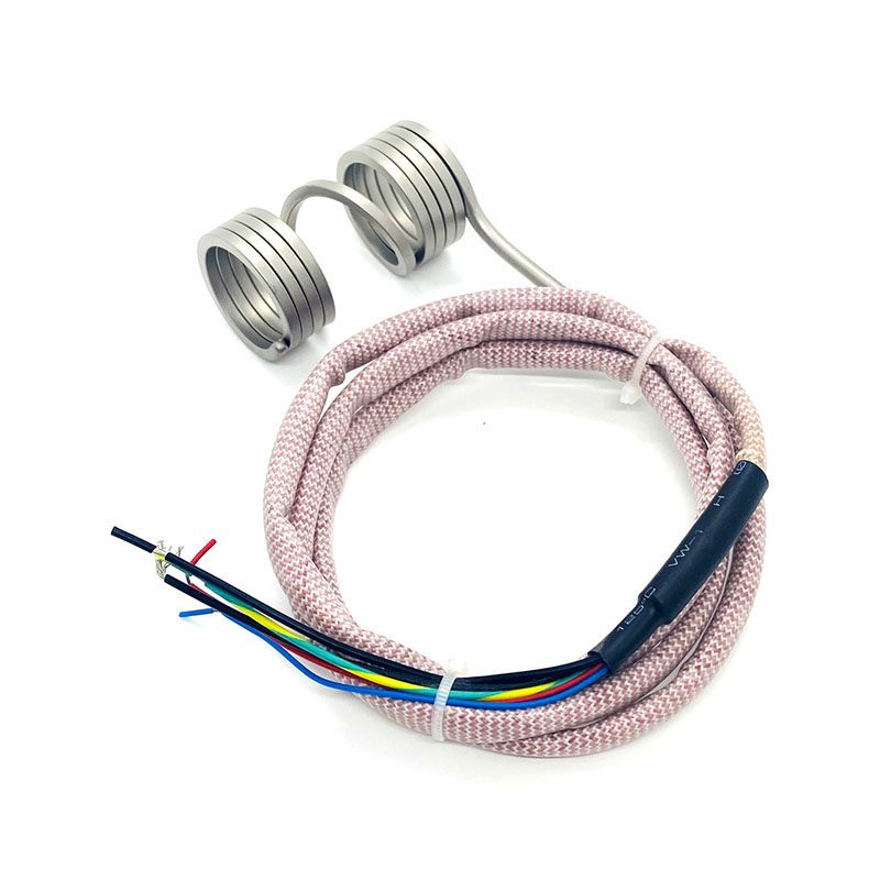
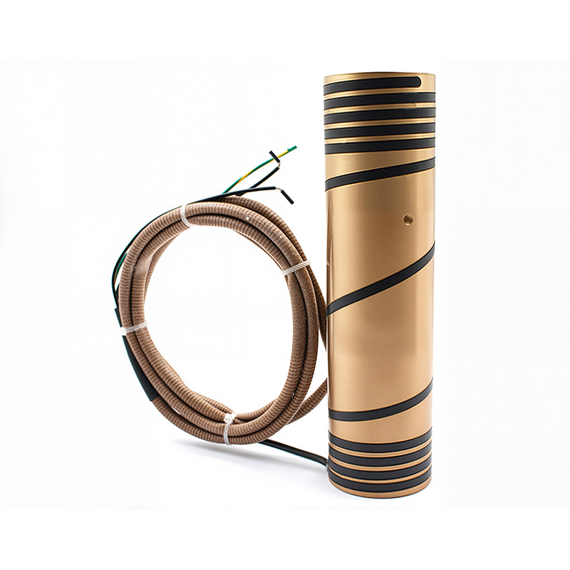
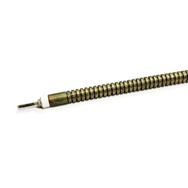
An armored heating cable, also called a mineral insulated heating cable, is built from three layers. At the centre sits a resistance conductor, usually a nickel-chromium or copper-nickel alloy chosen for stable resistance over temperature. Around it is compacted magnesium oxide, an excellent electrical insulator and a good conductor of heat. The outer layer is a seamless metal sheath drawn down to its final diameter, commonly somewhere between 3 and 10 mm. The finished cable is made to a fixed length, with a cold lead of low-resistance conductor at one or both ends so that the heating section sits only where heat is wanted.
These layers give the cable properties that polymer-insulated products cannot match. It tolerates sheath temperatures of several hundred degrees, resists crushing and abrasion, and has no organic insulation to age. It can be bent around valves and flanges, cast into a heating plate, or wrapped around a reactor shell. The one weakness is moisture: magnesium oxide absorbs water from the air, so the end seal and the cold-lead joint must stay intact from the factory until the day the cable is energised.
The sheath alloy is the first selection decision, because it sets both the temperature limit and the corrosion resistance. The figures below are typical planning values; the rating published for the exact cable always governs.
| Sheath material | Typical maximum sheath temperature | Typical use | Watch out for |
|---|---|---|---|
| Copper | about 250 °C | Freeze protection, mild process heating | Oxidises above its limit; poor in chemical atmospheres |
| Stainless steel 304 / 316 | about 600 to 800 °C | Food, pharmaceutical and general process lines | Chloride stress corrosion, especially on 304 |
| Alloy 825 (nickel-iron-chromium) | about 600 °C | Acidic and sulphur-bearing environments | Higher cost per metre |
| Alloy 600 (nickel-chromium-iron) | about 1,000 °C and above | Furnaces, high-temperature tooling | Cost; end-seal care at high temperature |
Sizing an armored heating cable from heat loss
Cable length is easy to measure; cable power is the part people guess. Start with heat loss per metre of pipe, using Q = 2π × k × ΔT ÷ ln(r2 ÷ r1), where k is the insulation conductivity, ΔT is the difference between the maintain temperature and the lowest ambient temperature, r1 is the pipe outer radius and r2 is the outer radius of the insulation. The example below holds a DN50 steel pipe at 150 °C in a winter ambient of −10 °C.
| Parameter | Value |
|---|---|
| Pipe and insulation | DN50, 60.3 mm outer diameter, 50 mm mineral wool, k = 0.055 W/m·K |
| Temperature difference | 150 − (−10) = 160 K |
| Radius ratio | ln(80.15 ÷ 30.15) = 0.978 |
| Calculated heat loss | about 57 W per metre |
| With 20 percent margin | about 68 W per metre |
| Segment of 50 m at 230 V | 3.4 kW, 14.8 A, circuit resistance 15.6 Ω |
| Sheath power density (6 mm cable) | about 0.36 W/cm² |
The surface power density is the number that protects the process. A 6 mm cable has about 188 cm² of surface per metre, so 68 W per metre works out near 0.36 W/cm², comfortable for a stainless sheath in most non-flammable fluids. Flammable liquids, polymers and heat-sensitive products need a much lower figure, which means a longer cable at lower power per metre.
Valves, flanges and pipe supports lose more heat than straight pipe, so add roughly 10 to 20 percent of equivalent length around each one or loop extra cable over them. Because resistance is fixed at manufacture, an armored cable cannot be shortened on site without changing its power. Measure the cold resistance on arrival and compare it with the data sheet; the tolerance is commonly in the range of −5 to +10 percent.
Extension wire and compensating wire are not the same thing
A thermocouple produces a tiny voltage that depends on the temperature difference between the measuring junction and the reference junction at the instrument. Running the thermocouple’s own wire all the way to the cabinet is rarely practical: noble-metal wire is expensive and heavy-gauge base-metal wire is bulky. Instead, the thermocouple head is joined to a cable that reproduces the same thermoelectric behaviour over a limited temperature range. That cable is what most buyers call compensation wire, and the term actually covers two distinct products.
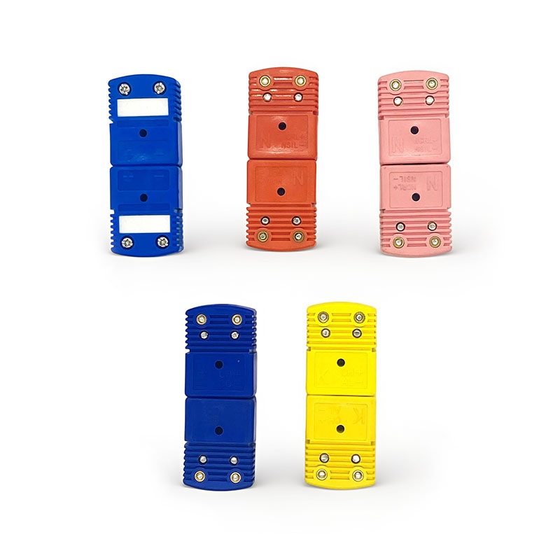
Extension cable (grade X) uses the same nominal alloys as the thermocouple, only in a form made for cabling. Compensating cable (grade C) uses different, cheaper alloys that merely match the thermocouple’s output at low temperature; it is the solution for types S, R and B. Neither grade can be swapped for the other, or for a cable of another thermocouple type.
| Thermocouple | Cable grade | Positive / negative conductor | IEC sheath | ANSI sheath | Typical cable range |
|---|---|---|---|---|---|
| K | KX extension | nickel-chromium / nickel-aluminium | green | yellow | −25 to 200 °C |
| J | JX extension | iron / copper-nickel | black | black | −25 to 200 °C |
| T | TX extension | copper / copper-nickel | brown | blue | −25 to 200 °C |
| E | EX extension | nickel-chromium / copper-nickel | violet | purple | −25 to 200 °C |
| N | NX extension | nickel-chromium-silicon / nickel-silicon | pink | orange | −25 to 200 °C |
| S and R | SC / RC compensating | copper / copper-nickel | orange | green | 0 to 100 °C |
| B | BC compensating | copper / copper | grey | grey | 0 to 100 °C |
Tolerance matters as much as type. For type K extension cable, IEC 60584-3 allows about ±60 µV for class 1 and ±100 µV for class 2, which is roughly ±1.5 °C and ±2.5 °C. On a loop that must hold ±5 °C, spending half the error budget on the cable alone is unwise, so specify class 1 wherever accuracy counts.
Why the cable zone matters: reading the thermocouple curve
Type K output rises almost linearly, about 40 µV per °C near room temperature, to 41.3 mV at 1,000 °C. The shaded band in the chart marks the range where extension cable is guaranteed to match the thermocouple. Inside the band, cable and thermocouple agree; outside it the cable’s alloys drift away from the thermocouple’s behaviour, so errors grow quickly.
The practical rule follows directly: make the joint between thermocouple and cable in a cool spot, such as a terminal head mounted off the hot surface, never inside the insulation jacket beside the heating cable. A joint that sits at 300 °C turns an accurate cable into an unpredictable one.
How wiring mistakes turn into temperature errors
Three mistakes account for most field errors. Plain copper wire between the thermocouple head and the controller moves the effective reference junction from the cabinet to the head, so the reading falls short by roughly the temperature difference between the two. With the head at 80 °C and the cabinet at 25 °C, that is about 55 °C low. Reversed polarity is worse: the cable subtracts what it should add, so the error is about twice the same difference, around 110 °C in this example. A wrong grade, such as type J cable on a type K thermocouple, produces errors that change with temperature, so the loop can pass a single-point check and still fail in production.
Notice the direction of the error. A reading that is too low makes the controller add power the process does not need, and on an armored heating cable that pushes the sheath toward its limit. This is why an independent high-limit sensor on a separate loop is not optional equipment on a heated line.
Insulation, shielding and routing around heaters
Compensation wire often runs along the same hot surface as the heating cable, so its jacket must be chosen for that environment, not for the cabinet. The chart shows typical continuous ratings; the data sheet of the actual cable governs.
In wet areas choose a fluoropolymer or a jacketed construction, and where abrasion is likely add a stainless steel braid over the cable. Remember that the cable’s own rating is separate from the accuracy range in the earlier table: a glass-fibre cable may survive 480 °C, but its thermoelectric match to the thermocouple still holds only inside the rated zone.
Heating power is often switched by solid-state relays or phase-angle controllers, which radiate noise in exactly the range that disturbs millivolt signals. Use twisted-pair cable with an overall shield and ground the shield at the controller end only, so that no ground loop forms. Keep at least 300 mm between the sensing cable and any power cable in parallel runs, and cross them at right angles when they must meet. For runs beyond about 100 m, a head-mounted transmitter that converts the signal to 4 to 20 mA is more robust than a longer length of millivolt cable.
Where to put the control and limit sensors
Place the control thermocouple on the pipe or vessel wall at a point that represents the process, normally away from the heating cable itself, because the sheath is always hotter than the product. On a pipe, that means the side opposite the cable and clear of valves, supports and other heat sinks. Fix it with stainless steel banding and cover it with insulation so that the junction reads the pipe, not the surrounding air.
Fit a second, independent high-limit thermocouple on the heater sheath at the hottest point, wired to its own limiter that cuts power at a fixed value. Set that value below the lowest of three numbers: the sheath rating, the degradation temperature of the product, and, in hazardous areas, the temperature class limit of the zone. Keep the control and limit loops on separate cables so that one fault cannot disable both. If the control loop reads 50 °C low because of a wiring error, the limit loop is the only thing standing between the cable and its maximum rating.
Commissioning checks that catch problems early
Most failures of armored heating cables and their sensing loops can be found in the first hour of commissioning if the right checks are made before the insulation goes on.
- Measure the cold resistance of the heating cable and compare it with the data sheet, both before and after fitting insulation.
- Test insulation resistance at 500 V or 1,000 V DC before wrapping. A fresh, dry cable usually reads far above 100 MΩ; a low reading points to moisture in the magnesium oxide, often at the end seal.
- Check the polarity of every thermocouple loop by warming the junction with a hand or heat gun. The reading must rise; if it falls, the polarity is reversed.
- Confirm that the controller’s input type matches the thermocouple, since type K and type J inputs look identical on the terminal strip.
- Compare readings with a calibrated reference at two points, for example an ice bath and a dry-block at process temperature.
- Record cable tags, resistance values, insulation readings and loop checks so that later faults can be compared with the commissioning baseline.
Troubleshooting common symptoms
| Symptom | Likely cause | First check |
|---|---|---|
| Reading low by a steady 30 to 60 °C | Copper wire or brass terminals in the sensing path | Inspect every splice and terminal for non-thermocouple material |
| Reading falls when the head warms | Reversed polarity | Swap the two conductors at one end and retest |
| Error grows with temperature | Wrong cable grade or wrong thermocouple type | Compare cable marking with the thermocouple type and controller setting |
| Unstable, jumping readings | Unshielded cable near switched power, or shield grounded at both ends | Check shield grounding and separate the routes |
| Heater trips ground-fault protection | Moisture in the insulation or a damaged end seal | Insulation resistance test and seal inspection |
| Circuit current below the calculated value | Resistance above data sheet, loose connection or damaged cold lead | Measure cold resistance at the terminals |
| Sheath runs hotter than expected | Poor contact with the pipe, missing insulation, or a sensor reading low | Verify the sensing loop before touching the heater |
When armored cable is worth the extra cost
Polymer-insulated heating cables cost less per metre and can be cut to length on site, but their exposure temperature generally tops out around 200 to 250 °C. Armored cables cost more and must be ordered to exact length, yet they handle far higher temperatures, mechanical abuse and long service lives. They are the practical choice when the maintain temperature is above about 150 °C, when steam purging or cleaning will push surface temperatures up, when mechanical damage is likely, or when the cable must be embedded or bent tightly.
In return you accept stricter requirements: exact lengths decided in advance, moisture protection at every termination, and a sensing loop accurate enough to protect the sheath. A failed armored cable under insulation is costly to locate, because lagging must be stripped back before a fault can even be found. Spending an extra hour on the thermocouple loop and its compensation wire is far cheaper than spending a day on that repair.
Frequently asked questions
Can I use ordinary copper wire instead of thermocouple compensation wire?
No. Copper forms a new junction with each thermocouple leg, so the reference point moves from the cabinet to the thermocouple head and the reading is low by roughly the temperature difference between the two. With the head at 80 °C and the cabinet at 25 °C, the error is about 55 °C. Type B is the one case where the compensating grade is copper in both legs, but it still has to be specified and marked as compensating cable.
What is the difference between extension cable and compensating cable?
Extension cable uses the same nominal alloys as the thermocouple and is used for base-metal types such as K, J, T, E and N. Compensating cable uses different, cheaper alloys that only match the thermocouple’s output at low temperature and is used for types S, R and B. The two grades are not interchangeable.
How long can a thermocouple compensation cable run be?
There is no fixed limit. A 0.5 mm² type K pair has a loop resistance near 2 Ω per metre, so 100 m adds about 200 Ω, which is only 0.02 percent of a 1 MΩ controller input. Noise is the real constraint. Beyond roughly 100 m, a head-mounted transmitter with a 4 to 20 mA output is the more reliable choice.
Can an armored heating cable be cut to length on site?
Generally no. Resistance and power are fixed per metre at manufacture, so cutting the heating section changes the output and exposes the magnesium oxide to moisture. Order the cable to the measured length with an allowance for valves and flanges, and trim only the cold lead if the manufacturer’s instructions allow it.
How often should the heating cable and sensing loop be tested?
Test cold resistance and insulation resistance at installation, after any maintenance that touches the cable, and then at least once a year, more often in wet or corrosive areas. Check the thermocouple loop against a calibrated reference annually or on the schedule of your quality system, and prove the high-limit trip point at the same visit.