

 English
 中文简体
 русский
 Español
 عربى





Huadong: Established in 1986
Inquiry Us Now
News&Inspiration
Contact Us
How a hot runner heater works?
Content
- 1 Main Parts of a Hot Runner System
- 2 What Happens in One Cycle
- 3 Hot Runner vs Cold Runner
- 4 Types of Hot Runner Systems
- 5 Hot Runner Heater Types Compared
- 6 The Hot Runner Coil Heater: Construction and Benefits
- 7 Temperature Control and Zones
- 8 How to Specify a Hot Runner Heater
- 9 Installation and First Heat Up
- 10 Troubleshooting Heater and Hot Runner Problems
- 11 Maintenance Schedule for a Hot Runner
- 12 Safety Points
- 13 Frequently Asked Questions
- 13.1 1. How does a hot runner work?
- 13.2 2. What does a Hot runner heater do?
- 13.3 3. What is a hot runner coil heater?
- 13.4 4. What voltage and wattage does a hot runner coil heater use?
- 13.5 5. Why does my hot runner heater keep burning out?
- 13.6 6. What is the difference between hot runner and cold runner molds?
- 13.7 7. What is the difference between an open gate and a valve gate?
- 13.8 8. How do I check a hot runner heater?
- 13.9 9. How long should I wait for a hot runner to heat up?
- 13.10 10. What should I send a supplier to order a replacement heater?
A hot runner is a heated manifold and a set of heated nozzles built into an injection mold that keep the plastic molten all the way from the machine nozzle to the gate of each cavity, so no runner solidifies and gets thrown away every cycle. The molten plastic enters through a heated sprue bushing, flows through channels in a temperature controlled manifold, passes through heated nozzles, and enters the cavity through a small gate. Between shots, the plastic in the manifold and nozzles stays at melt temperature, and only the part freezes. Heaters and thermocouples, controlled by a multi zone controller, hold each zone within a few degrees of its set point.
The result is less material waste, shorter cycles for many parts, better control of filling, and the ability to mold from the center of a part. The cost is a higher mold price, more maintenance, and a need for careful temperature control. At the center of every system is the heater. A Hot runner heater supplies the energy that keeps the melt flowing, and the hot runner coil heater, wrapped around each nozzle, is the most common type for nozzle heating. The sections below explain the parts, the cycle, the heater types, how to size and specify a heater, and how to troubleshoot problems.
Main Parts of a Hot Runner System
| Part | Function | Heating Method |
|---|---|---|
| Hot sprue bushing | Receives melt from the machine nozzle and feeds the manifold | Band, coil, or cartridge heater |
| Manifold | Steel block with melt channels that distributes plastic to each nozzle | Tubular, cast in, or cartridge heaters |
| Nozzles (drops) | Carry melt from the manifold to the gate | Coil heater, band heater, or integrated heater |
| Nozzle tip and gate insert | Form the gate where melt enters the cavity | Heat from the nozzle body |
| Valve pins and actuators | Open and close the gate on valve gate systems | Not heated, driven by air, oil, or electric power |
| Thermocouples | Measure the temperature of each zone | Not heated, send signals to the controller |
| Temperature controller | Switches power to each heater to hold the set point | Not heated, uses PID control |
| Insulation and spacers | Limit heat loss into the cooled mold plates | Air gaps and low conductivity supports |
What Happens in One Cycle
- Injection: the machine screw pushes melt through the sprue bushing into the manifold and then into each nozzle.
- Filling: melt passes through the gate and fills the cavity. In a valve gate system, the pin lifts to open the gate, and in an open gate system, the melt flows freely.
- Packing: pressure holds more melt in the cavity as the plastic cools and shrinks. The gate must stay open long enough to pack the part.
- Gate closing: the gate freezes, or the valve pin closes, which seals the cavity and stops flow back into the nozzle.
- Cooling and ejection: the part cools in the cavity and is ejected. The melt in the manifold and nozzles stays hot and ready.
- Next shot: the screw recovers, and the cycle repeats. The only plastic that solidified was the part.
The gate is where the heat balance matters most. It must be hot enough to let melt through, yet cool enough to freeze cleanly when the cycle ends. Too hot, and plastic leaks out as drool or stringing. Too cold, and the gate freezes early, causing short shots and sink marks.
Hot Runner vs Cold Runner
| Feature | Hot Runner | Cold Runner |
|---|---|---|
| Material waste | Almost none, no runner to scrap | Runner scrap each cycle, to regrind or discard |
| Cycle time | Often shorter, not limited by runner cooling | Can be longer when the runner is thick |
| Mold cost | Higher, with the system and controller | Lower |
| Maintenance | More, heaters and thermocouples wear | Less |
| Color or material change | Slower, melt stays in the manifold | Faster |
| Process control | Better balance, gating options, sequential filling | Simpler, runner design limits it |
| Best for | High volume, multi cavity, high cost resin | Low volume, frequent color changes, heat sensitive resin |
A Simple Savings Example
Take an 8 cavity mold making 5 gram parts. The parts weigh 40 grams per shot, and a cold runner adds about 12 grams, so the runner is about 23 percent of the total material. At a 15 second cycle, there are 240 shots an hour. A hot runner avoids 12 grams per shot, which is 2.88 kilograms an hour, or about 17.3 tonnes over 6,000 production hours. At 2 USD per kilogram of resin, that is about 34,600 USD a year. These figures are illustrative, but the same method lets you estimate the payback of a hot runner. If it adds 20,000 USD to the mold cost, it pays back in under a year in this example.
Types of Hot Runner Systems
- Open gate (thermal gate or hot tip): the gate is a simple opening, and it freezes between shots. It is simple, low cost, and suits many parts, but it can leave a small gate mark.
- Valve gate: a pin closes the gate mechanically. It gives a clean gate surface, allows sequential filling, and suits large or cosmetic parts and viscous resins, but it costs more and needs actuators.
- Externally heated nozzles: heaters wrap around the nozzle body, such as a hot runner coil heater. They give even heat and a flow channel free of obstructions, and they are the most common.
- Internally heated nozzles: a heater inside the melt channel heats the plastic from the center. They are compact, but they can create flow resistance and are less common.
- Multi tip nozzles: one nozzle feeds several gates, which suits small parts at a tight pitch.
- Balanced manifolds: channels are laid out so every nozzle receives melt at the same time and pressure, which is essential for consistent multi cavity parts.
Hot Runner Heater Types Compared
The Hot runner heater is the part that keeps each zone at temperature. Different shapes suit different locations.
| Heater Type | Typical Location | Strengths | Limits |
|---|---|---|---|
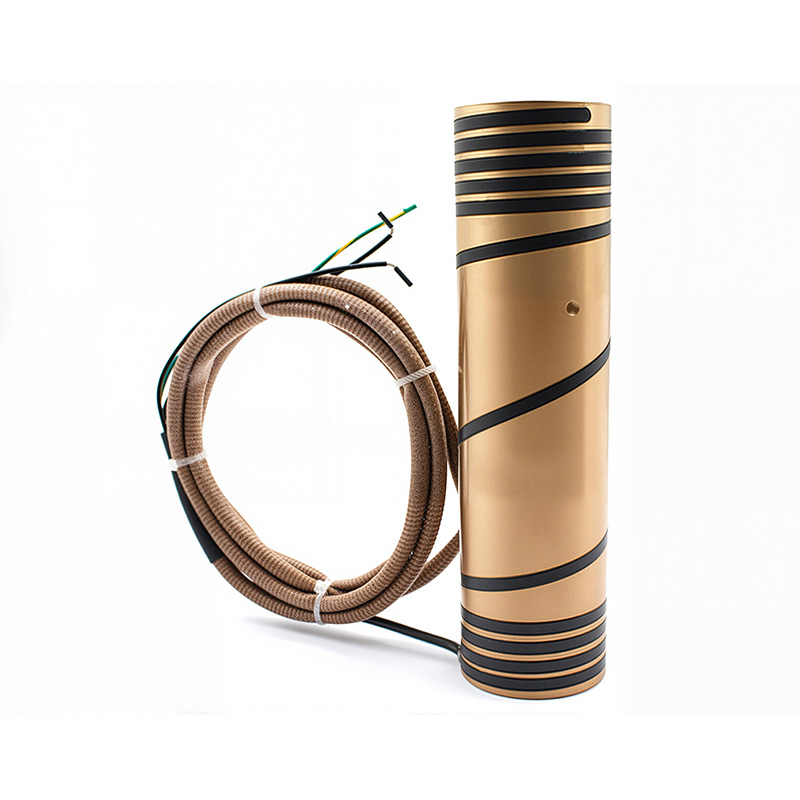
| Coil heater | Around nozzles | High power density, fast heat up, even heating, adjustable pitch | Needs an exact fit, can fail if overheated or contaminated |
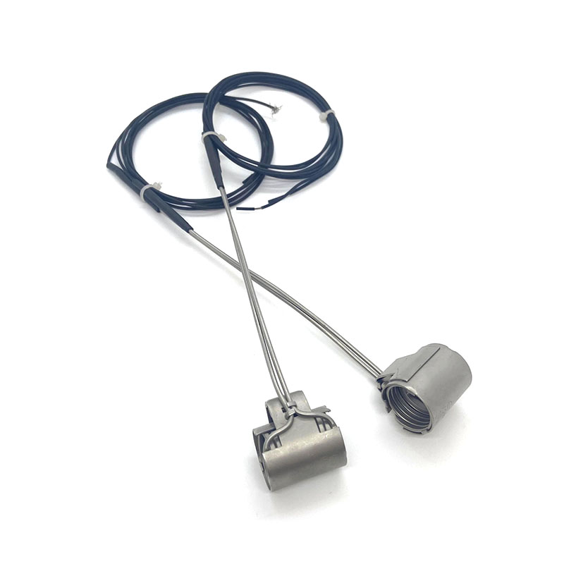
| Band heater | Sprue bushing, large nozzles | Simple, easy to replace | Lower power density, hot spots if the fit is loose |
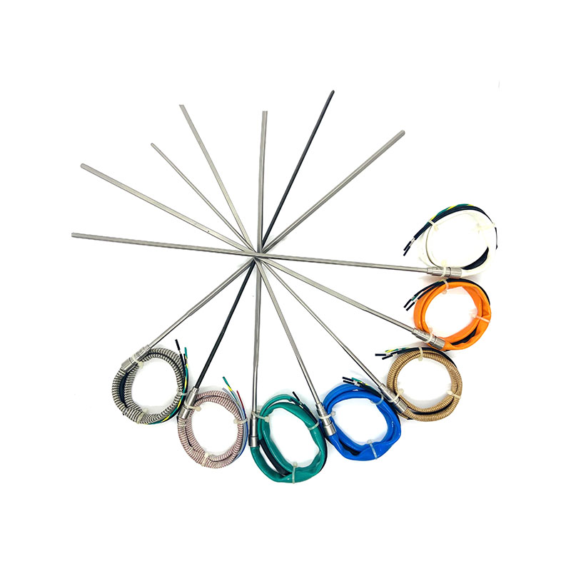
| Cartridge heater | Inside manifold or bushing bores | Compact, high watt density | Needs a tight bore, hot spots if it loosens |
| Tubular heater | Pressed into manifold grooves | Covers large areas, flexible shapes | Hard to replace once pressed in |
| Thick film heater | Integrated on nozzle bodies | Very even heat, compact | Costly, repairs are difficult |
The Hot Runner Coil Heater: Construction and Benefits
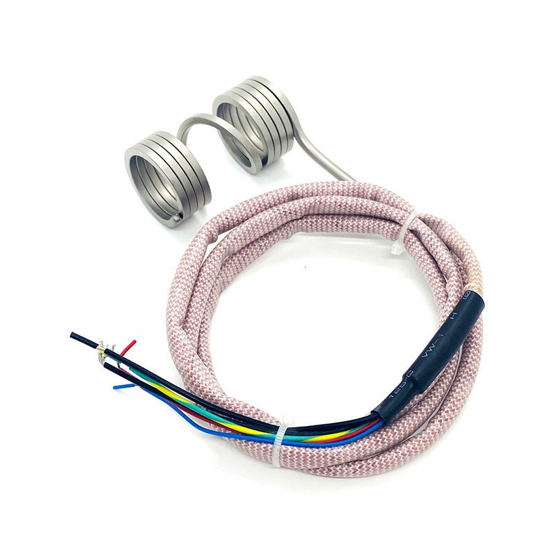
A hot runner coil heater is a spiral wound heating element that wraps around a nozzle body, like a spring. It is usually made from a tubular element: a resistance wire, often nickel chromium, runs along the center of a metal sheath and is surrounded by compacted magnesium oxide, which conducts heat well and insulates electrically. The tube is then formed into a coil with a precise inside diameter that fits the nozzle.
Why Coil Heaters Are Popular for Nozzles
- Even heat around the nozzle: the coil surrounds the nozzle, so heat enters from every side, which keeps the melt temperature uniform around the channel.
- Adjustable power profile: the pitch can be made tighter near the tip and at the ends, where heat loss is greatest, and wider in the middle. This gives a flat temperature along the nozzle.
- High power density: it delivers a lot of heat in a small space, which helps heat up quickly and recover after each shot.
- Custom fit: inside diameter, length, lead position, and lead length can be tailored to a given nozzle.
- Built in sensing: a thermocouple can be placed in the nozzle body or under the coil for accurate control.
- Clean design: leads can exit at any angle and run through channels in the mold plates.
Sizing a Heater: A Worked Example
Heater power must cover two needs: heating the steel to temperature in a reasonable time, and replacing the heat that is lost to the mold, the air, and the plastic. A quick estimate for heat up uses the mass of steel, its specific heat, and the temperature rise. Take a 20 kilogram manifold with a specific heat of about 0.5 kilojoules per kilogram per kelvin, heated from 20 to 250 degrees Celsius. The energy is 20 times 0.5 times 230, which is 2,300 kilojoules, or about 640 watt hours. Heating it in 30 minutes needs at least 1.28 kilowatts, and real systems fit 3 to 5 kilowatts or more to cover losses and heat up faster. Nozzle coil heaters are often in the range of about 100 to 600 watts each, depending on nozzle size, resin, and design.
Resistance helps you check a heater. Resistance equals voltage squared divided by power. A 230 volt, 400 watt heater should measure about 132 ohms, and a 120 volt, 300 watt heater should measure about 48 ohms. A reading far from the nominal value, within the maker's tolerance of about 10 percent, signals a fault or a wrong part.
Temperature Control and Zones
Each heater zone has a thermocouple and a control loop. Most controllers use PID control, which adjusts the power continuously to hold the set point. Common thermocouples are type J and type K, and the polarity must be correct. A reversed thermocouple will show a falling temperature when the zone heats up.
The set point depends on the resin. Hot runner zones are usually set at or slightly above the melt temperature, and the gate area may be set differently. The ranges below are typical melt temperature ranges, and the resin data sheet takes priority.
| Resin | Typical Melt Temperature Range | Note for Hot Runners |
|---|---|---|
| PP | 200 to 250 degrees Celsius | Forgiving, wide process window |
| PE | 190 to 240 degrees Celsius | Watch for drooling at open gates |
| ABS | 210 to 260 degrees Celsius | Avoid long residence times |
| PC | 280 to 320 degrees Celsius | Needs high power and good insulation |
| PA66 | 270 to 300 degrees Celsius | Narrow window, drool and freeze off risks |
| POM and rigid PVC | 170 to 220 degrees Celsius | Heat sensitive, needs tight control and smooth flow channels |
Thermal Expansion
Steel grows when it is heated. A manifold 400 millimeters long, heated from 20 to 250 degrees Celsius, grows by about 1.1 millimeters, using an expansion coefficient of about 12 micrometers per meter per kelvin. Hot runner designers allow for this by setting the nozzle position and the seal contact when the mold is hot, not cold. Heat the system to the working temperature, and let it soak before you start molding, so the seals settle and the dimensions stabilize.
How to Specify a Hot Runner Heater
When you order a replacement or a new heater, send the supplier a complete set of data. The table lists the items to include.
| Item | What to Provide |
|---|---|
| Voltage and power | Rated voltage, wattage, and tolerance |
| Inside diameter and fit | Nozzle outside diameter and the allowed clearance, often a small fraction of a millimeter |
| Length and shape | Heated length, total length, and any steps or cutouts |
| Power profile | Whether to concentrate power near the tip or the ends |
| Lead exit and length | Position, angle, length, and protective sleeve |
| Sheath material | Stainless steel or a high temperature nickel alloy for the highest temperatures |
| Thermocouple | Type J or K, position, and connector |
| Operating conditions | Maximum temperature, resin, and any exposure to moisture or resin leakage |
Whenever possible, send the old heater, a drawing of the nozzle, and a photo of the wiring. A heater that is slightly loose will run hotter than its setting, which leads to early burnout, and one that is too tight can not be installed.
Installation and First Heat Up
- Inspect and clean. Clean the nozzle surface and the heater bore of dirt and resin.
- Check the heater. Measure resistance and compare it with the nominal value. Measure insulation resistance to ground, which should be high, in the megohm range.
- Fit the heater. Slide the coil heater onto the nozzle, keep it in the right position, and route the leads without sharp bends or contact with hot edges.
- Place the thermocouple. Seat it in its hole and secure it so it reads the right temperature.
- Bake out moisture. If a heater has been in storage or a damp place, bring it up slowly at low power, around 100 to 120 degrees Celsius, for 20 to 30 minutes, so absorbed moisture leaves the insulation without causing a short.
- Heat up in stages. Raise temperature gradually and let the manifold soak, so the system expands evenly and the seals settle.
- Verify the zones. Check that each zone follows its set point and that the readings are stable.
Troubleshooting Heater and Hot Runner Problems
| Symptom | Likely Cause | What to Do |
|---|---|---|
| Zone does not heat | Open heater, blown fuse, loose connection | Measure resistance, check wiring and fuse |
| Temperature falls as the zone heats | Thermocouple reversed | Correct the polarity |
| Zone overshoots or swings | PID tuning, loose thermocouple, poor heater fit | Retune, reseat the thermocouple, check the fit |
| Heater burns out early | Loose fit, moisture, resin leak, overheating | Check the fit, bake out, fix leaks, lower the set point |
| Drooling or stringing at the gate | Gate too hot, no decompression | Lower the tip temperature, add suck back |
| Short shots or cold slugs | Gate freezing early, low zone temperature | Raise the tip temperature, check heater output |
| Resin leak at a nozzle | Thermal expansion mismatch, worn seal | Check the seal fit and alignment, replace worn parts |
| Black specks in parts | Degraded resin, dead spots, hot spots | Clean the manifold, reduce residence time, check temperatures |
Maintenance Schedule for a Hot Runner
- Every shift: check zone temperatures and look for alarms or drifting values.
- Weekly: inspect leads and connectors for damage, and check for leaks at nozzles.
- At each mold removal: measure heater resistance and insulation resistance, and inspect thermocouples.
- At each major service: pull the nozzles, clean the tips and gates, check seals, and replace worn parts.
- Before storage: clean the system, protect it from moisture, and store with a record of heater values.
- Keep spares: keep a set of heaters, thermocouples, and seals for the molds you run most.
Safety Points
- Burn hazard: hot runner parts and molten plastic stay hot for a long time after the power is off. Use protective gloves and allow cooling.
- Electrical safety: lock out the power before you work on a mold, check the ground, and use qualified staff.
- Fume and leaks: degraded resin can give off fumes, so ventilate the area, and stop the process if a leak occurs.
- Use correct heaters: do not exceed the rated voltage or temperature of a heater, and do not run an unconnected heater in free air.
Frequently Asked Questions
1. How does a hot runner work?
A hot runner keeps plastic molten in a heated manifold and heated nozzles, so melt flows from the machine to each cavity gate without a runner freezing. Only the part solidifies, which saves material and often shortens the cycle.
2. What does a Hot runner heater do?
It supplies the energy that keeps the manifold, nozzles, and sprue bushing at melt temperature. Controlled with a thermocouple and a multi zone controller, it holds each zone within a few degrees of its set point.
3. What is a hot runner coil heater?
It is a spiral wound tubular heater that wraps around a hot runner nozzle. It gives even heat around the nozzle, a high power density, and a tailored power profile, and it is the most common heater for nozzles.
4. What voltage and wattage does a hot runner coil heater use?
Common supplies are 230 volts or 120 volts, and some systems use 24 volts. Nozzle coil heaters are often about 100 to 600 watts each. Use the rating given for your nozzle, and check the resistance, which equals voltage squared divided by power.
5. Why does my hot runner heater keep burning out?
Common causes are a loose fit, moisture in the insulation, resin leaking onto the heater, overheating, and damaged leads. Check the fit, bake out moisture, repair leaks, and confirm that the set point and the power match the nozzle.
6. What is the difference between hot runner and cold runner molds?
A hot runner keeps the runner molten and produces no runner scrap, while a cold runner lets the runner solidify and ejects it with each part. Hot runners cost more but save material, and they are best for high volumes.
7. What is the difference between an open gate and a valve gate?
An open gate freezes between shots and is simple and low cost. A valve gate uses a pin to close the gate, which gives a cleaner gate surface and more control, but costs more and needs actuators.
8. How do I check a hot runner heater?
Measure its resistance and compare it with the nominal value, which is voltage squared divided by power, within about 10 percent. Measure the insulation resistance to ground, and inspect the leads and the thermocouple.
9. How long should I wait for a hot runner to heat up?
Often 20 to 40 minutes, depending on the system and resin, with a soak period so the manifold expands evenly. Heat up in stages, and follow the manufacturer's instructions for high temperature resins.
10. What should I send a supplier to order a replacement heater?
Send the voltage, wattage, nozzle outside diameter, heated and total length, lead position and length, thermocouple type, maximum temperature, and the resin used. If you can, send the old heater and a drawing of the nozzle.
PREV:What Is a Thermocouple Used For? Types, Plugs and Heads Guide
NEXT:Domestic Multi‑Point Thermocouples Achieve Technical Breakthrough
NEXT:Domestic Multi‑Point Thermocouples Achieve Technical Breakthrough
Recommended Products

Our factory mainly produces various series and specifications of temperature sensors, armored
thermocouple cables, hot runner mold electric heaters, armored heating cables, thermocouple compensation
wires (copper-coated), and special equipment for the temperature instrument industry.
-
 +86-0577-62312532
-
 ben@china-h.com
sales03@china-h.com -
 Hongqiao Shifan Industrial Zone, Yueqing City, Zhejiang, China
Let's Work Together
Copyright © Yueqing Huadong Instrument And Meter Factory
All Rights Reserved.
 Custom Armored Thermocouple Cables Manufacturers